Thursday, June 9, 2011
Roszak Designs New Gallery at the Alder Planetarium
Saturday, June 4, 2011
7RR, a green home by Thomas Roszak Architecture
Thursday, February 3, 2011
Green, Modern and Affordable House

Monday, October 25, 2010
IIT students assist Lycée Français de Chicago on future school design and construction

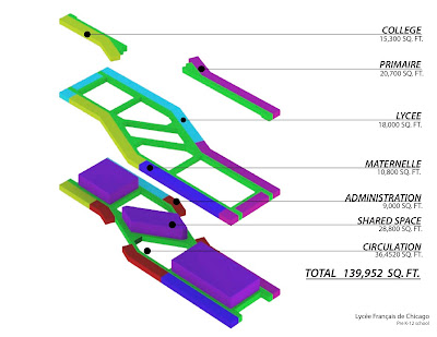
Our firm, Thomas Roszak Architecture, worked with the Lycée Français de Chicago (LFC) and students from the Illinois Institute of Technology (IIT) as part of a comprehensive building design studio to study the future facility needs of this private pre-K thru 12 French school. With help from LFC’s facility board we studied various sites that were proposed by Jones Lang LaSalle, their real estate consultant, to determine actual site requirement in terms of size and access. We studied and improved on preliminary programs to pinpoint space allocation between grades and support spaces. This is a school with needs for over 700 students. The book The Third Teacher was a required reading as preparation for the assignment. We studied hard and soft costs and made recommendations that will surely be implemented into the final design and construction. The 14 students, in their 4th and 5th year of their Bachelor of Architecture program also prepared plans, renderings, budgets, proformas, zoning analysis, code analysis, and detailed construction details. A final architectural crit was done in front of the LFC board and other Chicago area professionals including architects, contractors, and school officials that gave informative real world insight into the design of this school and the future of education in general. A learning experience for all...


 Click here to download a PDF with more images.
Sunday, October 17, 2010
An Engineer Imagines in Glass
An interview discussing the structural glass stair design between Architect, Thomas Roszak principal at Thomas Roszak Architecture, LLC and Structural Engineer, Koz Sowlat, principal at Sowlat Structural Engineers, Chicago. See also previous blog on this project.
 Describe the Members and Materials:
· Laminated glass: Each structural panel is Laminated Glass; made of ASTM C 1048 Fully Tempered (FT) and Heat Strengthened (HS) glass plies bonded with a clear interlayer in conformance with ASTM C1172.
· Composition: Vertical panels, landing panel, and treads, all have the same laminated glass composition, each measuring 1 ½ in. thick, and composed of the following three plies: 1/2" FT + 1/2" HS + 1/2" FT. A combination of glass types was selected to provide appropriate performance under service conditions as well as under extreme conditions.
Describe the Structural Analysis and Design:
· Analysis method: Three-dimensional finite element analyses were used to determine stresses and displacements, under design loads. For vertical panels, large-deformation, non-linear analysis was used, to account for member flexibility.
· Design method: At each element, von Mises stress (vector sum of principal stresses) was determined and maintained below the allowable stresses.
· Allowable Stress: For each load case and for each load combination, von Mises stress within the structure was limited to 5,000 pounds per square inch for FT glass, except that stress in FT with surface conditioning was limited to 2,500 pounds per square inch. Fully tempered glass is produced with a residual surface compression of 9,700 pounds per square inch, reducing the likelihood of surface tension, and inhibiting opportunities for crack growth.
· Composite Action: Based on standards recommended by The Institution of Structural Engineers, London, UK, entitled: “Structural Use of Glass in Buildings,” published in 1999, each panel was analyzed as if a solid material.
· Redundancy: General structural integrity check was provided, in conformance with the City of Chicago Building Code, Section 16(13-52-040,) by considering each panel with one ply removed and subject to selfweight.
Describe the Service Design Loads:
· Public stairs: City of Chicago Building Code loads for public stairs were used, allowing 100 ponds per square foot simultaneously on all treads and the landing panel. Additional analysis allowed two 300-lb persons standing on any tread or the landing panel.
· Handrail loads: Concentrated load of 200 lbs in any direction at any point, or simultaneous vertical and horizontal thrust of 50 pounds per linear foot.
· Footstep sideway push: Allowed one 200-lb concentrated load on any tread.
· Footstep forward push: Allowed one 200-lb concentrated load on any tread.
· Wind pressure: Design wind pressure was determined to be 14.4 pounds per square foot, based on consideration of the staircase within a tall building, where sliding doors allow external wind pressure to influence the internal wind pressure.
Describe the Perimeter Vertical Panels:
· Role: The perimeter vertical panels provide overall stability, as well as gravity support, for the staircase.
· Level 39 supports: Each vertical panel was detailed to rest within a base channel, secured to Level 39 concrete floor slab. Analyses considered floor rotation that would reduce contact area. Base channel was designed to carry loads caused by horizontal loads, in any direction, and by vertical loads.
· Level 40 supports: Each vertical panel is supported against horizontal loads, in any direction, at Level 40. The Level 40 connection was detailed with a vertical slip, such that differential deflections of Level 40 and Level 39 induce no additional stresses within the glass panels.
Describe the Interior Vertical Panel:
· Role: Interior vertical panels provide gravity support, but do not contribute to the overall staircase stability. The interior vertical panels are laterally supported by the perimeter vertical panels, using the connecting treads as struts.
Describe the Treads and the Landing Panel:
· Role: The treads and the landing panel provide gravity support, and are also pin-connected to the vertical panels to allow participation within the overall staircase stability system.
· Steel clips: Each clip is detailed to allow rotation of the horizontal panel in relation to the supporting vertical panel. The steel clips are detailed to allow a soft, gentle transfer of loads from glass to steel, carefully avoiding hard spots.
FIG. 1 - Perimeter Vertical Panel Stress Profile, Subject to Combined Loads

FIG. 2 – Landing Panel Stress Profile, Subject to the Weights of Two 300-lb Persons
Monday, October 11, 2010
Structural Glass Stair
Wednesday, August 18, 2010
ACBHM-The Glass Weave
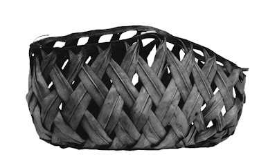
Fragile materials bind a tolerant society as a woven basket is held together with slender reeds. The glass weave is strong and resilient.
We enter the memorial and see three elements: the Atlantic Ocean, Journey Bridge and Starlight opening. Sunlight from the ocean refracts through the blocks, which illumine and darken with the day. Life is symbolized by light, human spirit by the flames of a candle. The glass blocks are the candles lit in remembrance.
The Journey Bridge is entwined in an unsettled weave of cedar beams. Under the Starlight opening, we travel the bridge while vulnerable to the elements. We struggle as with Jacob’s ladder to rise higher in this world and to overcome the human capacity for cruelty.
We recall the loss of life at times when tolerance has vanished. We move through this memorial, this place and time and gather our awareness. We bring only our memories and values into the memorial. It stands without embellishment.
The GLASS WEAVE reminds us that life is fragile. Yet it reflects the enduring strength that we derive from our shared humanity.


 Architect: Thomas Roszak Architecture, LLC
Structural Engineer: Werner Sobek
ACBHM and a PDF with greater detail can also be found at http://roszak.com/Thomas_Roszak_Architecture/Projects/Pages/ACBHM.html


